


FreeScan Combo: Reverse Engineering of carbon fiber molds and components
In this case study we want to illustrate an entire 3D scanning and reverse engineering process, which focuses on dimensional control and reconstruction of geometry editable in a CAD environment. The case study was created in collaboration with F&N COMPOSITI, a company specialized for over 20 years in the industrialization and production of composite components for the aerospace, nautical and industrial sectors.
The objects to be scanned were: a carbon fiber mold for the creation of a bike fork (ZASH model), useful for dimensional control in relation to the CAD model, and the fork made with this mold to carry out Reverse Engineering. In this regard, it is good to explain the entire process of creating these two models.
The design and creation of a mold often constitute the largest economic and time investment to start a production, and for this reason at F&N COMPOSITI the production of the molds has been internalized, using composite materials; this allows a reduction in initial costs and a large time gain in the prototyping and start-up of production phase. An equally important factor is the composite mold, extremely lighter, which shares the same chemical and physical properties of the material with the final product, guaranteeing minimal expansion of the products and avoiding having to scale the model during the mold design phase.
After the design we move on to the model creation phase, milled on an epoxy board with a density of 900kg/m3. The models are treated with a sealer and then with release wax; Once these finishing steps have been completed, we move on to lamination with the use of pre-impregnated material. Before going into operation, the mold is checked to guarantee the geometric tolerances required by the project and is treated with a release paste. This last procedure is then repeated in sequence with each subsequent mold.

The fork, like all components of ZASH bikes, is a monocoque. This involves the design and division of the mold into two parts, so as to be able to laminate and couple the entire product before curing in the autoclave, where an internal bag expands and thanks to the closed mold applies pressure on the surfaces of the product. A carbon prepreg in different weights and textures is used to guarantee dimensional and torsional stability and an excellent finish. Once the product has been extracted from the autoclave, it is detached from the model and a second cycle is carried out, the post-cure where the mould, in a much longer time with a higher temperature than that of future operation, acquires the properties necessary to be able to resist the numerous work cycles.

FreeScan Combo 3D scanner
The scanner used is Shining3D's new FreeScan Combo, used for inspections with metrology-level precision, reverse-engineering, additive manufacturing and other applications in many manufacturing sectors, including automotive, aerospace, rail transportation, heavy industry, manufacturing mould, foundry and medical industry.
Why the Combo
The main difference between structured light scanning and laser scanning is in the method of acquiring three-dimensional data. Structured light scanning uses patterns of light projected onto the object, while laser scanning measures distance using a laser beam. Both techniques can produce high-quality results, but the choice between them depends on the specific needs of the application, the size of the object and the precision required. In essence, laser scanning is more accurate, as it is able to capture very small details, but the precision depends on the power of the laser and the quality of the acquisition sensor. The difficulty of this case study is precisely that of scanning black objects and with reflective surfaces like the mold shown previously. To work on the mesh in the Reverse Engineering phase it is advisable to use a scan in high resolution "0.2mm" mode. This type of scan requires the use of markers. The volumetric accuracy, on the other hand, is 0.02+0.033mm/m, i.e. the deviation between the real model and the digital one.
3D Scanning
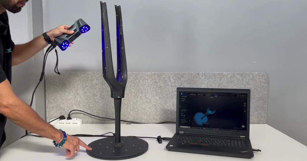
The scanning mode used is laser scanning with 26 parallel lines, applying the markers randomly.
The fork was also scanned through a laser scan, using a turntable to allow the scanner to acquire circular or symmetrical geometries. The markers on the turntable are used as a reference for the lower part, while the markers on the model are used to acquire the upper part.

Post processing
Once the scan was finished, all the details that are not part of the scanned object were eliminated and the point cloud was generated. Subsequently the mesh was generated, with high quality, closing the areas where the markers are present.

Finally, it is possible to carry out operations on the mesh such as simplification, optimization, and automatic or manual closing of the holes.

Once this is done, save the work and export the scan in STL or OBJ format.
Quicksurface
Quicksurface is used to convert scanned 3D data into CAD models. It is a solution for Reverse Engineering that integrates any 3D scanner that can export STL files, or PTX (Point Cloud) files. The problem with some software is that they do not allow you to work with meshes, because they cannot manage huge quantities of points and therefore are difficult to manipulate. Boolean operations and other types of operations cannot be applied. So it is necessary to use this information in the correct way by inserting it into these mesh inspection software before obtaining the editable model that can be used in the CAD environment.

Here too it is possible to operate with the mesh edit commands to close any holes in the scanned model. But the software allows you to align the scanned model against the CAD model to perform metrological inspections. For accurate alignment you can use a point alignment, which allows me to select a minimum of 3 points in the same order and in the same area for both models. The software then performs the alignment automatically.

Through the "Compare" command, the software creates a graph that shows the deviation between the two models at each point on the screen, also allowing you to set the desired tolerance value.

For the fork, however, the operations to be carried out are different. First of all it is important to reconstruct the mesh by closing the holes or areas where there are voids. And Quicksurface does this optimally through the Edit Scan command. The command allows a homogeneous closure and possibly, in the presence of curvatures or complex features, it is possible to increase the extension of the area to be closed in such a way as to involve the adjacent mesh triangles, and then close. Alternatively, it is possible to use the “Bridge” option, which allows optimized closure in mesh areas that present discontinuities.

Subsequently the fork was rebuilt entirely through a command that allows you to extract the sections along the entire model. By reproducing the 2D sketch of all sections and with the help of geometric primitives, i.e. planes, you can use the loft command for accurate reconstruction, section by section.

It may also be useful to make a comparison between the mesh and the reconstructed model to evaluate the deviation.

Finally, it is possible to export a file in STEP format that can be edited in a CAD environment, such as Autodesk Fusion 360.

Results and conclusions
With the laser scanning carried out using the Combo it was possible to very quickly detect extremely complex details, for example on the fork, thanks to the great ability of the laser to acquire large quantities of data in a short time. From this point of view, the Combo is very advantageous since the resolution is influenced by the point cloud, the precision of the sensors and the acquisition source and therefore the higher the resolution, the more detailed and precise the data acquired by the scanner will be.
Therefore, both meshes obtained are of high resolution and very accurate compared to the CAD model. Quicksurface allowed the reconstruction of the fork using surface shortcuts, reproducing editable geometry in Autodesk Fusion 360.


Leave your comment